B3.3 Mechanical Systems Application And Selection [HL]
B3.3.1 – Concept: Mechanical Advantage
What is Mechanical Advantage?
Mechanical Advantage (MA) describes how much a mechanical system multiplies the force applied to it.
Mechanical systems allow us to move or lift heavy loads using less effort.
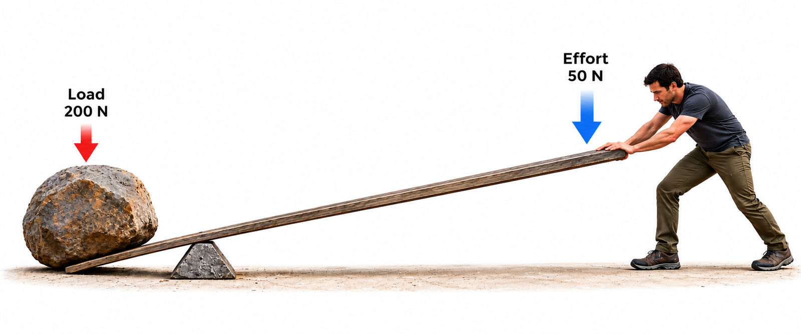
Practical Example: Using a Lever
Imagine lifting a heavy rock that requires a force of 200 N.
By using a lever, you only need to apply 50 N to lift the same rock.
The lever allows you to lift the load with less effort by multiplying the applied force.
Calculating Mechanical Advantage
Mechanical Advantage is calculated by dividing the output force by the input force.
MA=Output ForceInput ForceWhere:
- Input Force (Effort): The force applied to the mechanism.
- Output Force (Load): The force exerted by the mechanism on the load.
Worked Example
A lever produces an output force of 200 N when an input force of 50 N is applied.
MA=20050=4The Mechanical Advantage is 4.
This means the lever multiplies the applied force by four.
Interpreting Mechanical Advantage
| Mechanical Advantage | Meaning | Effect |
|---|---|---|
| MA > 1 | Force is multiplied. | Less input force is required, but output speed or distance is reduced in an ideal system. |
| MA = 1 | No force multiplication. | Input and output forces are equal. |
| MA < 1 | Force is reduced. | Output speed or distance can be increased in an ideal system. |
Relationship Between Force and Speed
Mechanical systems cannot create energy.
In an ideal mechanical system:
- Increasing output force reduces output speed or distance.
- Increasing output speed or distance reduces output force.
For example, a lever can multiply the applied force, but the effort must move through a greater distance than the load.
Key Takeaway
Mechanical Advantage indicates how much a mechanism multiplies or reduces the applied force.
A higher MA means greater force multiplication, usually at the expense of output speed or distance.
Mechanical Advantage has no units because it is a ratio between two forces.
Activity – Mechanical Advantage in Everyday Products
Activity: MA > 1 vs MA < 1
Mechanical systems can be designed to increase either output force or output speed.
1. Mechanical Advantage > 1
Identify an everyday product that uses MA > 1.
- Name the product.
- Explain how it increases the output force.
2. Mechanical Advantage < 1
Identify an everyday product that uses MA < 1.
- Name the product.
- Explain why increasing speed or movement is more important than multiplying force.
Show Possible Answers
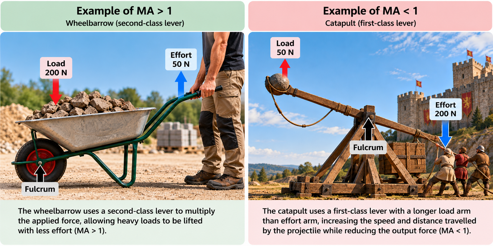
MA > 1 – Wheelbarrow
A wheelbarrow uses a second-class lever to multiply the applied force, allowing heavy loads to be lifted with less effort.
MA < 1 – Catapult
A catapult can use a lever with a longer load arm than effort arm, increasing the speed and distance travelled by the projectile while reducing the output force.
Key idea: MA > 1 increases force, while MA < 1 can increase speed or distance.
B3.3.1 – Mechanical Advantage: Gears
1. What are Gears?
Gears are toothed wheels that transmit rotational motion and torque between shafts.
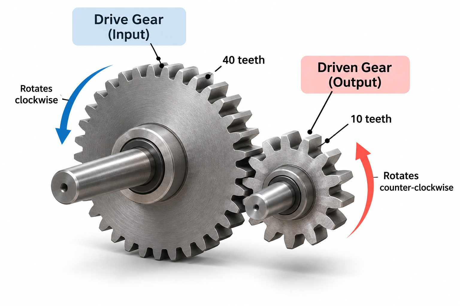
When two gears mesh, the teeth of one gear push against the teeth of the other, causing it to rotate.
Gears have three main functions:
- Change rotational speed: Increase or decrease the speed of rotation.
- Modify torque: Increase or decrease the turning effect of a force.
- Change rotational direction: Two meshing external gears rotate in opposite directions.
What is Torque?
Torque is the turning effect of a force around an axis.
For example, when using a spanner to tighten a nut, the applied force produces torque.
Torque depends on both the applied force and its perpendicular distance from the axis of rotation.
2. Drive Gear vs Driven Gear
A simple gear system consists of two gears:
| Component | Definition | Function |
|---|---|---|
| Drive Gear (Input) | The gear that receives the input motion. | Transfers rotational motion to the next gear. |
| Driven Gear (Output) | The gear that receives motion from the drive gear. | Produces the output rotation. |
Practical Example
Consider two connected gears:
- Drive Gear: 40 teeth.
- Driven Gear: 10 teeth.
When the drive gear rotates, it causes the driven gear to rotate.
Because the driven gear has fewer teeth, it completes more revolutions than the drive gear.
Result: The driven gear rotates faster.
3. Gear Ratio
The Gear Ratio (GR) describes the relationship between the number of teeth on the driven gear and the drive gear.
GR=Number of teeth on driven gearNumber of teeth on drive gearExample A – Increasing Speed
A gear system consists of:
- Drive Gear: 40 teeth.
- Driven Gear: 10 teeth.
Interpretation:
- The driven gear completes 4 revolutions for every revolution of the drive gear.
- Output speed increases by a factor of 4.
- Output torque decreases to one-quarter of the input torque in an ideal system.
Purpose: Increase rotational speed.
Example B – Increasing Torque
A gear system consists of:
- Drive Gear: 10 teeth.
- Driven Gear: 40 teeth.
Interpretation:
- The drive gear completes 4 revolutions for every revolution of the driven gear.
- Output speed decreases to one-quarter of the input speed.
- Output torque increases by a factor of 4 in an ideal system.
Purpose: Increase output torque.
4. Relationship Between Speed and Torque
Gears allow mechanical systems to exchange rotational speed for torque.
Increasing output speed reduces output torque, while increasing output torque reduces output speed.
| Gear System | Output Speed | Output Torque | Mechanical Advantage |
|---|---|---|---|
| Large drive gear → Small driven gear | Increases | Decreases | MA < 1 |
| Small drive gear → Large driven gear | Decreases | Increases | MA > 1 |
| Equal-sized gears | Remains equal | Remains equal (ideal) | MA = 1 |
Mechanical Advantage in Gear Systems
For an ideal gear system:
MA=Output TorqueInput TorqueMechanical Advantage can also be calculated using the number of teeth:
MA=Teeth on driven gearTeeth on drive gearTherefore, for an ideal gear system:
MA=GRReal Mechanical Systems
Real gear systems experience energy losses due to friction and other mechanical effects.
As a result, the actual output torque is lower than the theoretical value predicted by an ideal gear system.
5. Activity – Gear Ratio and Mechanical Advantage
Activity: Understanding Gear Systems
A mechanical system consists of two connected gears:
- Drive Gear: 15 teeth.
- Driven Gear: 45 teeth.
Answer the following questions:
- Calculate the Gear Ratio (GR).
- Determine the Mechanical Advantage (MA) of the ideal system.
- Does the system increase speed or torque?
- How many revolutions does the drive gear complete for every revolution of the driven gear?
Show Solution
1. Gear Ratio
GR=4515=32. Mechanical Advantage
For an ideal gear system:
MA=GR=33. Speed or Torque?
The system increases torque and reduces rotational speed.
4. Number of Revolutions
The drive gear completes 3 revolutions for every revolution of the driven gear.
Conclusion: The gear system multiplies the output torque by 3 while reducing the output speed to one-third of the input speed.
6. Key Takeaway
Remember
- Gears transmit rotational motion and torque between shafts.
- The drive gear provides the input motion; the driven gear produces the output motion.
- Gear Ratio describes the relationship between the number of teeth on the two gears.
- MA > 1: Output torque increases and rotational speed decreases.
- MA < 1: Output speed increases and torque decreases.
- In an ideal gear system, Mechanical Advantage = Gear Ratio.
Gears cannot increase both speed and torque simultaneously without additional energy input.
B3.3.1 – Mechanical Advantage: Pulleys
1. What is a Pulley?
A pulley is a simple mechanical device consisting of a grooved wheel and a rope or cable that runs around it.
Pulleys are commonly used to lift heavy loads, change the direction of an applied force, or reduce the effort required to move an object.
A pulley system typically consists of:
- Pulley wheel: A grooved wheel that guides the rope or cable.
- Rope or cable: Transmits the applied force through the system.
- Effort (Input Force): The force applied to pull the rope.
- Load (Output Force): The weight or resistance being lifted.
There are three main types of pulley systems:
- Fixed pulleys.
- Movable pulleys.
- Compound pulley systems.
2. Fixed Pulley
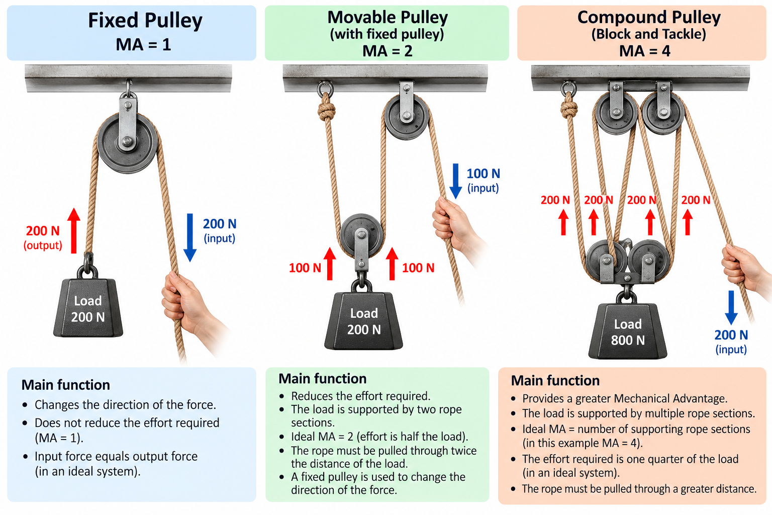
A fixed pulley is attached to a stationary support and does not move with the load.
Its main purpose is to change the direction of the applied force, making it easier to lift an object.
For example, pulling a rope downwards can lift a load upwards.
In an ideal fixed pulley:
MA=1This means that the input force is equal to the output force.
Worked Example – Fixed Pulley
A fixed pulley is used to lift a load weighing 200 N.
Calculate the effort required to lift the load.
Step 1 – Mechanical Advantage
MA=1Step 2 – Calculate the input force
MA=Output ForceInput Force 1=200F F=200 NConclusion: A fixed pulley changes the direction of the force but does not reduce the effort required in an ideal system.
3. Movable Pulley
A movable pulley is attached to the load and moves together with it.
Unlike a fixed pulley, a movable pulley can reduce the effort required to lift a load.
In a simple movable pulley system, the load is supported by two sections of rope.
Therefore, in an ideal system:
MA=2This means that the effort required is half the weight of the load.
Worked Example – Movable Pulley
A movable pulley is used to lift a load weighing 200 N.
Calculate the effort required.
Step 1 – Mechanical Advantage
MA=2Step 2 – Calculate the input force
MA=200F 2=200F F=100 NConclusion: The movable pulley reduces the effort required to lift the load by half.
Force and Distance
A movable pulley reduces the effort required, but the rope must be pulled through a greater distance.
For example, to lift a load by 1 metre, the effort end of the rope must move 2 metres in an ideal system with MA = 2.
Mechanical systems exchange force for distance; they do not create energy.
4. Compound Pulley Systems
A compound pulley system, also known as a block and tackle, combines fixed and movable pulleys.
These systems are used when a greater Mechanical Advantage is required.
They are commonly found in:
- Construction cranes.
- Sailing boats.
- Industrial lifting equipment.
- Workshop hoists.
The Mechanical Advantage of an ideal pulley system can be determined by counting the rope sections supporting the moving load.
MA=Number of supporting rope sectionsImportant
Count only the rope sections that directly support the moving pulley block.
Do not simply count the number of pulley wheels.
The Mechanical Advantage depends on how the rope is arranged.
Worked Example – Compound Pulley
A compound pulley system has 4 rope sections supporting the moving load.
The load weighs 800 N.
Calculate the effort required to lift the load.
Step 1 – Identify Mechanical Advantage
MA=4Step 2 – Calculate the input force
MA=Output ForceInput Force 4=800F F=200 NConclusion: The pulley system allows an 800 N load to be lifted with an ideal effort of only 200 N.
5. Comparing Pulley Systems
| Pulley System | Main Function | Ideal Mechanical Advantage | Effect |
|---|---|---|---|
| Fixed Pulley | Changes force direction. | MA = 1 | No reduction in effort. |
| Movable Pulley | Reduces input force. | MA = 2 | Effort is halved. |
| Compound Pulley | Provides greater force multiplication. | Depends on rope arrangement. | Allows heavier loads to be lifted with less effort. |
6. Activity – Calculating Mechanical Advantage
Activity: Understanding Pulley Systems
A construction worker uses a compound pulley system to lift a heavy object.
The system has 5 rope sections supporting the moving load.
The load weighs 1,000 N.
Answer the following questions:
- Calculate the Mechanical Advantage (MA) of the ideal pulley system.
- Calculate the effort required to lift the load.
- If the load rises by 2 metres, how far must the rope be pulled?
- Explain why the pulley system reduces the effort required without creating additional energy.
Show Solution
1. Mechanical Advantage
The system has 5 supporting rope sections.
MA=52. Required Effort
MA=Output ForceInput Force 5=1000F F=200 N3. Distance Travelled by the Rope
In an ideal system:
Effort Distance=MA×Load Distance d=5×2 d=10 m4. Conservation of Energy
The pulley system reduces the input force but increases the distance through which the effort must act.
In an ideal system:
Input Work=Output Work 200×10=1000×2 2000 J=2000 JConclusion: The pulley system multiplies the applied force by 5, but the rope must travel 5 times the distance moved by the load.
7. Key Takeaway
Remember
- Fixed Pulley: Changes the direction of the applied force. Ideal MA = 1.
- Movable Pulley: Reduces the effort required. A simple movable pulley has an ideal MA = 2.
- Compound Pulley: Combines fixed and movable pulleys to achieve greater Mechanical Advantage.
- Mechanical Advantage: In an ideal pulley system, it equals the number of rope sections supporting the moving load.
- Force vs Distance: Increasing Mechanical Advantage reduces the required effort but increases the distance through which the rope must be pulled.
Pulleys make lifting heavy loads easier by exchanging force for distance, not by creating additional energy.